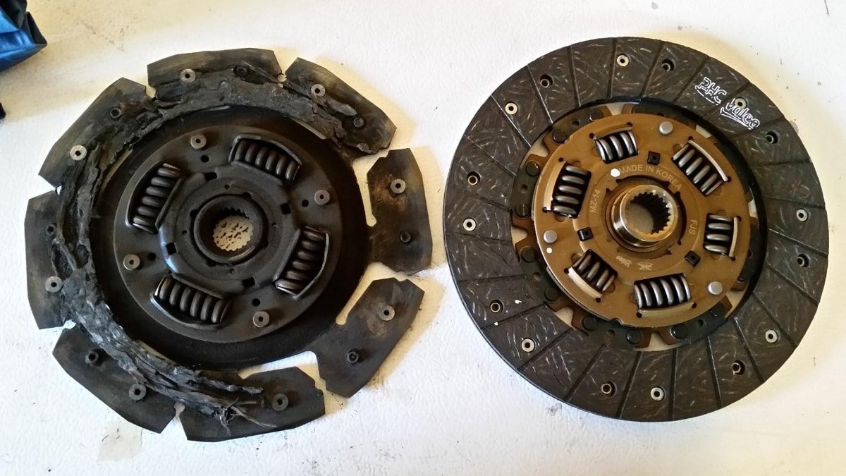
A clutch is a mechanical device that is used in automobile applications to engage and disengage power transmission especially from a driving shaft to a driven shaft. In easy words, clutches physically disconnect the flywheel (connected to the engine) from the gearbox (connected to wheels).
Types of clutches:
There are various types of clutches used for different applications. They are:
- Single plate clutch
- Multi-plate clutch
- Centrifugal clutch
- Semi-Centrifugal clutch
- Dog and spine clutch
- Hydraulic clutch
- Vacuum Clutch
Single plate clutch:
It is a type of clutch that consists of the use of only a single clutch plate (as the name suggests itself). It is a basic type of clutch system and the most common type of clutch used in vehicles. In a single plate, clutch power is transmitted by means of friction between the contact surface of a clutch plate.
Construction:
The single-plate clutch basically consists of a flywheel, pressure plate, clutch plate, clutch and friction lining, thrust, and ball bearing clutch spring, adjustable link, driving stud, and nut and bolt arrangement.
A flywheel is connected to the engine shaft and thus when the engine shaft rotates flywheel also rotates. The bolts are provided so as to connect the flywheel and pressure plate. The pressure plate is bolted to the flywheel through clutch springs and is free to slide on the clutch shaft when the clutch pedal is operated. There is a friction plate that is kept in between the flywheel and the pressure plate.
Working of single plate clutch:
When the clutch pedal is pressed, the spring gets compressed due to which the clutch plate is gripped between the flywheel and the pressure plate. The spring should be of more stiffness i.e. the property of a material by virtue of which it resists the elastic deformation. The friction linings are present on both sides of the clutch plate. Due to the friction between the flywheel, clutch plate, and pressure plate, the clutch plate also revolve around the flywheel, which also results in the revolving of the clutch shaft. The clutch shaft is connected to the transmission. Thus, the engine power is transmitted from the crankshaft to the clutch shaft.
When the clutch pedal is pressed, the pressure plate moves back against the force of the springs, and the clutch plate becomes free between the flywheel and the pressure plate. Thus, the flywheel remains rotating as long as the engine is running and the clutch shaft speed reduces slowly, and finally, it stops rotating. As soon as the clutch pedal is pressed, the clutch is said to be disengaged, otherwise, it remains engaged due to the spring forces.
Application:
1)Where there is a need to transmit a large amount of torque.
2) Cars, trucks, and heavy vehicles( as the space is not compact so a bigger diameter of a clutch plate can be used).
Advantages:
- The clutch response is fast as compared to a multi-plate clutch as there is only a single plate.
- Clutches engagement is instantaneous.
- It generates low heat.
- Higher coefficient of friction.
Disadvantages:
- Torque transmission is less as compared to a multi-plate clutch for a given amount of torque.
- It is an old type of clutch which was earlier widely used but now not so popular.
- Not used in small vehicles.
Read about everything related to Turbochargers. Click here.
Multi-plate clutch:
As the name suggests multi-plate, means more than a single plate. A multi-plate clutch is a type of clutch system in which multiple clutch plates are used to make frictional contact with the flywheel in order to transmit power between the shaft of the engine and the shaft of transmission of a vehicle.
Multiplate clutches use a number of clutch plates, instead of the single plate as seen in the single-plate clutch. As the number of clutch plates is increased, the friction surface also increases. The increased number of friction surfaces obviously increases the capacity of the clutches to transmit torque. The plates are arranged alternatively to the engine shaft and gearbox shaft. They are firmly pressed by strong coil springs and assembled in a drum. Each alternate plate slides in grooves on the flywheel and the other slides on splines on the pressure plate. Thus, each alternate plate has inner and outer splines.
The multi-plate clutch may be wet or dry. When the clutch is operated in an oil bath/quenching/ oil splash then it is called a wet clutch. Mostly multi-plate wet clutch will be seen in Manual transmission vehicles today.
Construction:
The system consists basically the same as that of a single plate clutch system. It consists of a set of clutch plates and pressure plates arranged alternatively, friction linings, thrust springs, fulcrum pin, spring, bearings, nut and bolt arrangement.
Working:
The working of multiple clutches is more or less the same as a single plate clutch. When the clutch pedal is pressed, the thrust springs do not move due to the stiffness provided by these springs maintaining some pressure over the pressure plate having friction lines on its inner surface. This pressure over the pressure surface the frictional contact between the friction lines of the pressure plate and the friction lines of multiple clutch plates is maintained due to which frictional force is applied over the flywheel.
The frictional force causes the frictional contact between the multiple clutch plates and the flywheel is maintained which in turn finally provides clutch engagement. When the clutch pedal is pressed the fulcrum attached at its inner end rotates due to which the inner splines sleeve through which the pressure plate is attached moves outward which in turn applies pressure over the thrust springs. Due to this force, the thrust springs move which in turn releases the pressure over the pressure plate, and finally, the frictional force between the pressure plate, clutch plate, and flywheel is removed. Due to this removal of the frictional force, frictional contact between the pressure plate, clutch plate, and flywheel breaks, and finally, the clutch is disengaged.
Application:
- The multi-plate clutch is used where compact space is desirable.
- Motorcycles, Scooters as there are less space and the system is compact.
Advantages:
- Higher torque transmission capacity and the plates are smaller due to their force to transmit torque than as compared to a single plate clutch which will be bigger for the same amount of torque transmission.
Disadvantages:
- The coefficient of friction is low.
- Clutch engagement is not instantaneous.
Centrifugal Clutch:
It is a type of clutch system in which centrifugal force is used to connect the engine (driving) shaft to the transmission (driven) shaft instead of the spring force for keeping it in the engaged position. (Though there are also centrifugal clutches that use springs force). This clutch engages more at high speeds. Centrifugal clutch does not require a clutch pedal for the operation of a clutch also the clutch is operated automatically depending upon the engine speed.
The vehicle can be stopped in gear without stalling the engine. Similarly, the vehicle can be started in any gear by pressing the accelerator pedal.
A centrifugal clutch consists of weights pivoted. When the engine speed increases the weight flies off due to the centrifugal force, operating the bell levels, which press the plate. The movement of the plate presses the spring, which ultimately presses the clutch plate on the flywheel against the spring. This makes the clutch engaged. The spring keeps the clutch disengaged at low speeds at about 500 rpm. The stopper limits the movement of the weights due to the centrifugal force.
Applications:
The Centrifugal clutch is used in some applications like
- Chain saw and lawn movers.
- Machines in some industries where the operation is non-manual and the operations are engaged automatically.
Advantages:
- Cheaper in cost.
- Operation is easy as the clutch is operated automatically depending upon the engine speed (rpm).
- It does not require any clutch pedal to operate the clutch.
- Lesser maintenance.
- It helps the engine and prevents it from getting stalled.
Disadvantages:
- There is some loss in power due to friction and slipping phenomena.
- Limited torque transmission capability. A high amount of torque cannot be transmitted due to the above point.
- There is an overheating problem due to automatic engagement and disengagement during the running conditions.
Semi-Centrifugal Clutch:
The semi centrifugal clutch uses both the forces i.e., centrifugal force as well as spring force for the clutch engagement. The clutch springs are designed to transmit the torque at normal speeds, while the centrifugal force assists in the transmission of torque at high speeds.
A centrifugal clutch consists of three hinged and weighted levers and three clutch springs alternatively arranged on the pressure plate. At normal speeds, when the power transmission is low, the springs keep the clutch engaged, the weighted levers do not have any pressure on the pressure plate. At high speed, when the power transmission is high, the weights fly off and the levers also exert pressure on the plate, keeping the clutch engaged firmly. Thus instead of having more stiff springs for keeping the clutch engaged firmly at high speeds, they are less stiff, so the driver may not get any type of strain while the operation of the clutch.
When the speed decreases, the weights fall and the levers do not exert any pressure on the pressure plate. Only the spring pressure is exerted on the pressure plate which is sufficient to keep the clutch engaged. An adjusting screw is provided at the end of the lever, by means of which the centrifugal force on the pressure plate can be adjusted.
Applications:
- Used in some heavy vehicles where torque transmission need is high.
- Some automobile cars.
Advantages:
- It uses both centrifugal force as well as spring force for different torque needs. Springs are designed to transmit the torque at lower engine speeds. Centrifugal force assists in torque transmission at higher engine speeds.
Disadvantages:
- The maintenance of the mechanism is somewhat difficult than the centrifugal clutch.
Diaphragm Clutch:
A Diaphragm clutch consists of a diaphragm on a conical spring that produces pressure on the pressure plate for engaging the clutch. The spring is either tapered finger type or crown type and is mounted on the pressure plate.
When the clutch is engaged, the spring pivots on the rear pivot rings as it is held in the clutch cover, so that its outer rings contact the pressure plate. In this conical position of the spring, the clutch plate remains gripped between the flywheel and the pressure plate.
When the clutch pedal is pressed, the throwout bearing moves towards the flywheel, pressing the center portion of the spring, which causes the rim to move backward. This removes the pressure on the pressure plate and the clutch is disengaged.
These type of clutches has some advantages over coil spring-type clutches. It needs no release levers and the spring itself acts as a series of levers. The pressure of the spring increases until the flat position is reached and decreases as this position is passed. The driver does not have to exert heavy pedal pressure to hold the clutch disengaged as with the coil spring type in which the spring pressure increases further when the pedal is depressed to disengage the clutch.
Applications:
- Used in automobile applications.
Articles you might love:
Supercharger | Definition, Types, Supercharging of engine
Hydraulic brakes: Basics, Principle, Working, Advantages, and Disadvantages
Dog & Spline Clutch:
This type of clutch is used to lock two shafts together or to lock gear to a shaft. It consists of a sleeve having two sets of internal splines. It slides on a splined shaft with smaller diameter splines. The bigger diameter splines match with the external dog clutch teeth on the driving shaft. When the sleeve is made to slide on the splined shaft, its teeth match with the dog clutch teeth of the driving shaft. Thus the sleeve turns the splined shaft with the driving shaft. The clutch is said to be engaged. To disengage the clutch, the sleeve is moved back on the splined shaft to have no contact with the driving shaft.
This type of clutch has no tendency to slip. The driven shaft revolves exactly at the same speed as that of the driving shaft, as soon as the clutch is engaged. Therefore, It is known as the positive clutch.
Application:
- Very less used. They are only used in applications when shaft locking is required or to lock two shafts in any application.
Advantages:
- They do not slip.
- Dog and Spline clutches can transmit a large amount of torque.
- They do not develop any heat during engagement and disengagement due to rigid locking.
- No friction is present as the two locked shafts rotate together.
Disadvantages:
- Engagement and disengagement of the clutch are not possible or very difficult at higher speeds.
- There is some sort of relative motion required for initial engagement and disengagement.
Electromagnetic Clutch:
The main parts of electromagnetic clutch are usually parts that are seen in basic electrical engineering applications. They are as follows:
- Rotor: It is the main part of the clutch assembly which is directly connected to the engine shaft( Driving member). It continuously rotates with the driving shaft i.e., the engine shaft.
- Winding: It is located behind the rotor. It does not rotate along with the rotor and remains stationary. A high voltage DC supply is connected with this winding which transfers a high voltage current into this winding and converts it into an electromagnet.
- Armature: The armature is located at the front side of the rotor. It is connected to the hub and is secured to the hub with the help of rivets or bolts.
- Hub: Hub is bolted with the transmission shaft(driven shaft) and rotates along with the driving shaft. It is positioned after the armature.
- Friction Plate: Friction plate is inserted between armature and rotor according to the requirement depending upon the power transmission.
- Supply unit: Supply unit is a type of unit which consists of a clutch switch, battery, wire, etc.
Working:
In an electromagnetic clutch, the flywheel consists of winding. The current is supplied in the winding from the battery or dynamo. When the current passes through the winding, it produces an electromagnetic field that attracts the pressure plate, thereby engaging the clutch. When the supply is cut-off, the clutch is disengaged. The gear lever consists of a clutch release switch. When the driver holds the gear lever to change the gear, the switch is operated cutting off the current to the winding which causes the clutch to disengage.
At low speeds when the dynamo output is low, the clutch is not firmly engaged. Therefore, three springs are also provided on the pressure plate which helps the clutch engage firmly at low speed also.
Applications:
Used in applications that do not require any type of linkage to actuate the clutch system.
Advantages:
- As there is no linkage required to operate the clutch it can be installed in remote direction.
- Easy to operate.
- Very less wear and tear during operation.
Disadvantages:
- The cost is high.
- Operating temperature is limited because the electrical components can not sustain high temperatures and have the risk of getting damaged.
Vacuum Clutches:
The clutch system operated through a vacuum is known as a vacuum clutch.
Main parts of vacuum clutch:
The main parts of vacuum clutch are as follows:
- Switch
- Solenoid
- Non-return valve
- Piston
- Vacuum cylinder
- Vacuum reservoir
- Battery or battery connection
- Inlet( from intake manifold) and outlet(to clutch through linkage)
Working:
The vacuum clutch is operated by a vacuum existing in the engine manifold. The vacuum clutch mechanism consists of a vacuum cylinder with a piston, solenoid-operated valve, reservoir, and a non-return valve. The reservoir is connected to the engine manifold through a non-return valve. The vacuum cylinder is connected to the reservoir through a solenoid-operated valve. The solenoid is operated from the battery and the circuit incorporates a switch that is placed in the gear lever. The switch is operated when the driver holds the lever to change gears.
When the throttle is opened, the pressure in the inlet manifold increases, due to which the non-return valve closes, isolating the reservoir from the manifold. Thus a vacuum exits in the reservoir all the time.
In the normal operation, the switch in the gear lever remains open and the solenoid-operated valve remains in its bottom position. In this position, the atmospheric pressure acts on both sides of the piston of the vacuum cylinder, because the vacuum cylinder is open to the atmosphere through a vent. When the driver holds the lever to change the gear, the switch is closed, energizing the solenoid which pulls the valve up. This connects one side of the vacuum cylinder to the reservoir. Due to the difference of pressure on the vacuum cylinder piston, it moves. This movement of the piston is transmitted by a linkage to the clutch, causing it to disengage. When the driver is not operating the gear lever, the switch is open and the clutch remains engaged due to the spring force acting on it.
Hydraulic Clutches:
The clutch operated through the oil pressure is known as a hydraulic clutch. The hydraulic clutch is operated in the same way as the vacuum clutch. The only difference is that it is operated by oil pressure whereas the vacuum clutch is operated by vacuum.
Main parts:
The mechanism of the hydraulic clutch consists of a cylinder with a piston, control valve, pump, accumulator, and oil reservoir. The piston is connected to the clutch by a linkage. The pump is operated by the engine itself. The oil from the reservoir is pumped into the accumulator tank. The accumulator tank is connected to the cylinder through the control valve. The control valve is electrically controlled by a switch in the gear lever.
Working:
When the driver holds the gear lever to change the gears, the switch is operated to open the control valve admitting the oil under pressure to the cylinder. Due to the oil pressure, the piston moves to cause the clutches to be disengaged. As soon as the driver leaves the gear lever, the switch is open which closes the control valve and the clutch is engaged.
Applications:
- Best suited for handling for high power/ high torque applications.
Advantages:
- When the clutch tends to fail the clutch pedal will have reduced play that will show at earliest that there is a problem with clutch operation.
- Self-adjusting for wear.
Disadvantages:
- Risk of master cylinder leakage.
- The cable-actuated mechanism suffers from the risk of under lubrication and requires constant care.
- The driver needs to check the clutch fluid level and top up periodically (more care than other types of clutches).
Also see Engine oils, their different grades and their uses.


